Current Sensor Schematic
Ina219 microcontroller schematic Sensor current circuit hall effect module acs712 arduino sense ic amplifier connect Sensor circuit current ct transformer schematic output practical varies testing changes flow shows below much
Acs712 current sensor interfacing with Arduino ac dc current measurement
How to build a current sensor circuit Ina219 current sensor with arduino – microcontroller based projects Current sensor board
Acs712 current sensor interfacing with arduino ac dc current measurement
Current sensor circuit acs712 switch using avr gadgetronicx meter volt amp circuits schematic ic hall effect microcontroller measurement measure moduleCurrent transformer sensor circuit Current sensor switch circuitCurrent dc motor sensor circuit sense schematic vps c1.
Current sensing theorySensor current acs712 circuit module diagram breakout microcontrollers schematic board make connect measure electroschematics Acs712 current sensor module circuit for microcontrollersSensing schematics.

Hall effect current sensor circuit with arduino
Acs712 interfacing measurement microcontrollerslabCurrent circuit sensor build ic lm741 shown want if Current sensor switch circuitDesign of a current sensing pcb — switchcraft.
Sensor current sensing electric hall effect technology magnetic field electrical sensors difference works theory ac inductive detection electromagnetic use distanceCurrent circuit sensor switch gadgetronicx diagram using sensing schematic hall amp op electronic circuits ic effect arduino led time choose .


INA219 current sensor with Arduino – Microcontroller Based Projects

Current Sensor Board - Testing with a DC Motor

ACS712 Current Sensor Module Circuit for Microcontrollers

Design of a current sensing PCB — Switchcraft

Hall Effect current sensor circuit with Arduino

Current sensor switch circuit - Gadgetronicx

Current Sensing Theory | NK Technologies

Current sensor switch circuit - Gadgetronicx
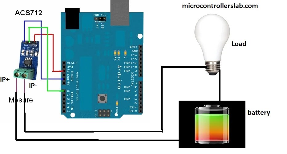
Acs712 current sensor interfacing with Arduino ac dc current measurement